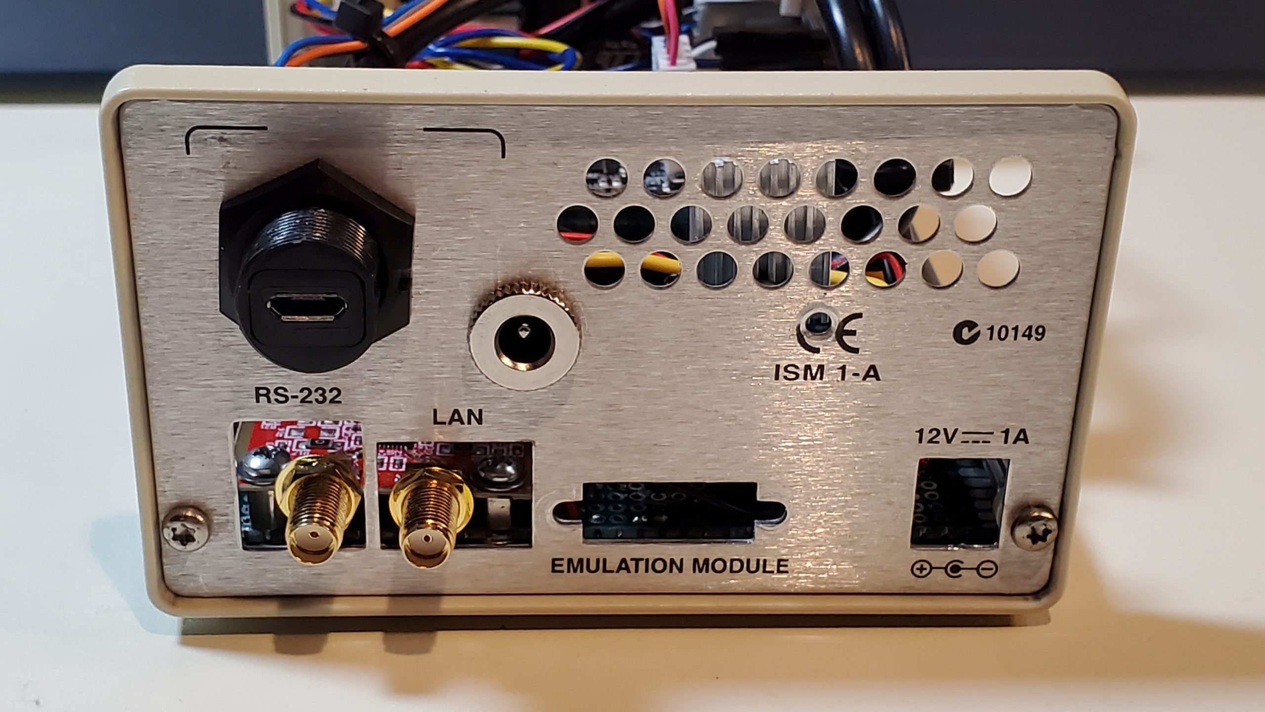
Economical DIY RF Wattmeter project variants are presented here to read forward and reflected power and calculate SWR for the VHF, UHF, and microwave bands. The variants presented here are working up to 10GHz and offer up to 11 calibration sets to cover a wide range of frequency bands with greater accuracy.
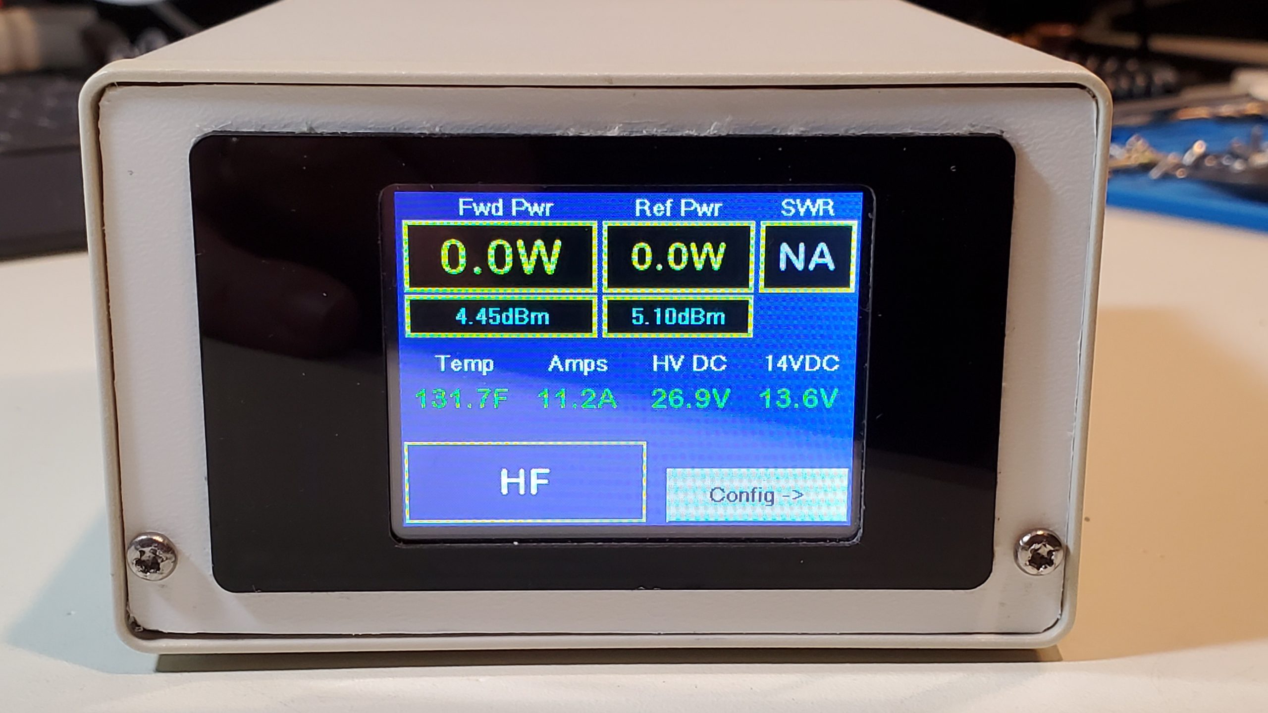
The meter works using a pair of inexpensive but accurate log power detectors connected to off-the shelf, usually surplus bi-directional couplers to convert the sampled RF power in the forward and reflected directions to a low voltage which is read by a CPU. Results are optionally displayed on a local screen of various types (OLED, LCD Graphics Touchscreen, LCD Character Text display, and/or remotely on a PC desktop application. The desktop app and local screens also control the CPU to load the best cal table values, perform calibration, update the firmware on a LCD touchscreen, configure alarm setpoints for measured values including DC voltages and temperature and even graph the power and SWR.
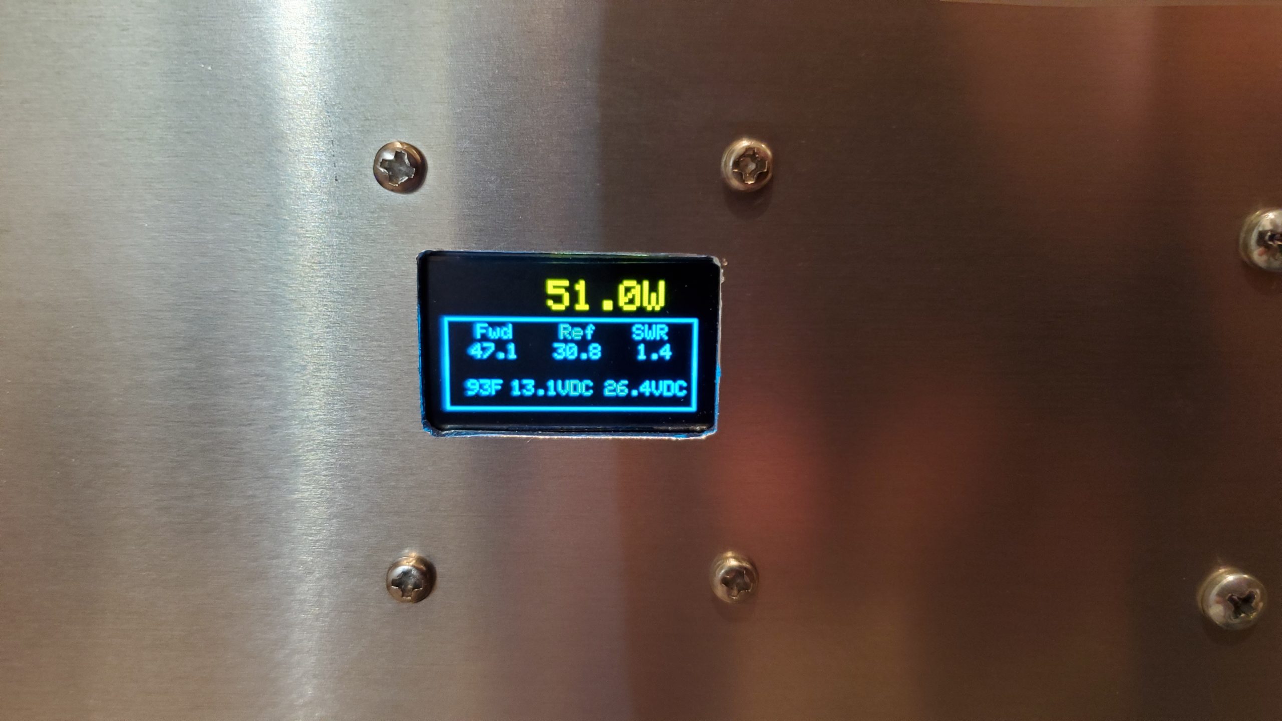
Accurate SWR/Power meters for these frequencies are rare above 144Mhz, especially above 500MHz. It is handy to have a readout in both dBm and Watts so you do not have to waste time converting between units.
RF milli-wattmeters measure only 1 input at a time and require attenuators to reduce power to the sensor usually less than 10dBm. The classic Bird/Sola Basic wattmeters using “slugs” and are easier to use, measure forward and reflected power with a quick twist of the slug and do not require attenuators to measure high RF power levels. They do require a good inventory of not inexpensive slugs since each slug is designed for a limited power level and frequency range. Many slugs are required to cover the range of VHF to Microwave bands we use. Modern Log power detectors cover 1 to 10Ghz with temperature compensation and a high degree of accuracy and can be found at relatively low cost.
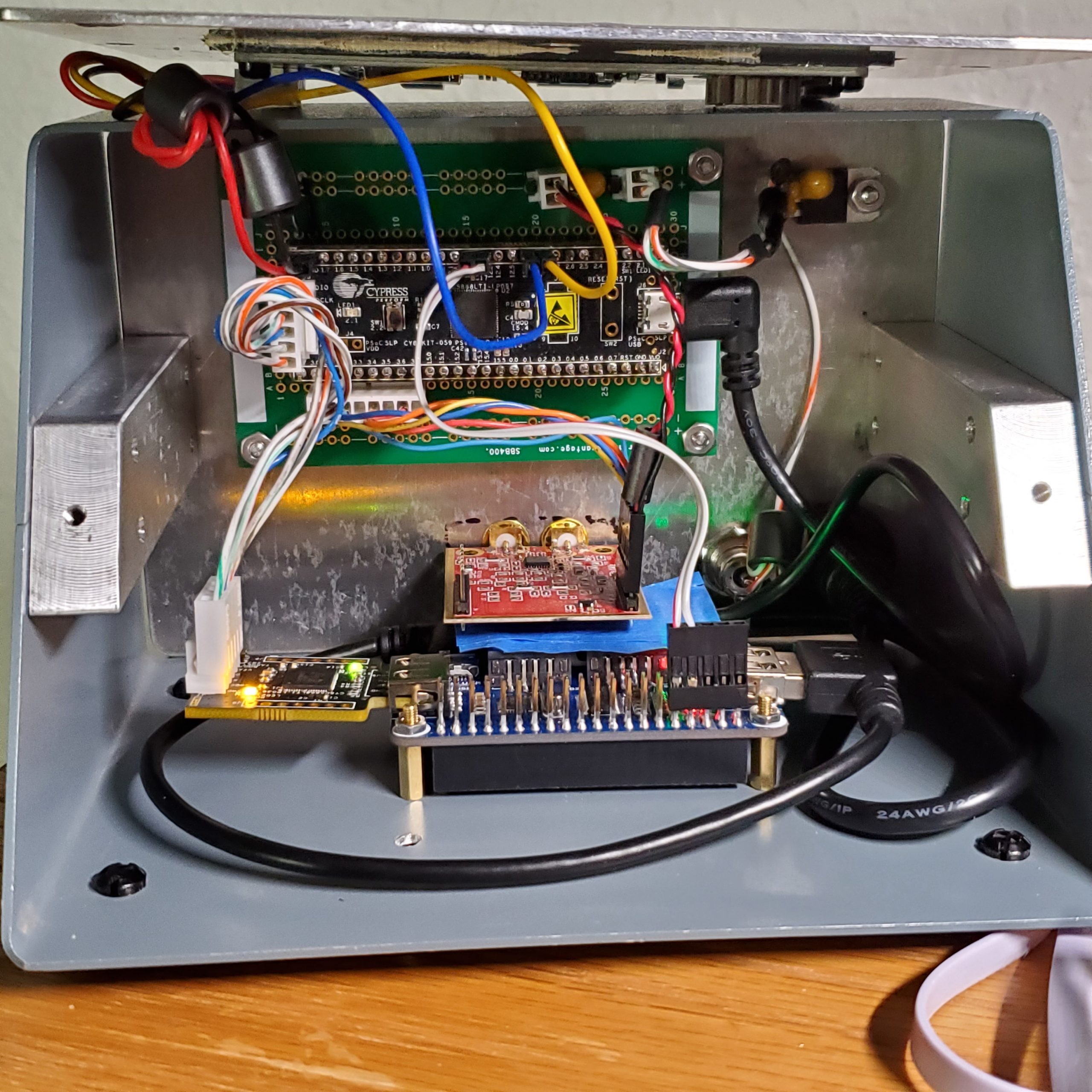
I have created various versions of my RF Wattmeter as the project capabilities have evolved. The first started on an Arduino with built in graphics and used the internal ADC which worked but was noisy and accuracy was modest. Later an external 16 bit ADC was added to greatly improve the results. In between I switched to the Cypress Semiconductors PSoC 5LP (Programmable System on Chip) for better results and a more capable development environment with full debugger. This is what I used for my earlier MultiBand LO published in Jan 202 QQEX and in some regional VHF conference proceedings. The CPU module used (CY8CKIT-059) costs about the same as the Arduinos but includes 2 CPUs chips and multiple ADC types including a 20bit ADC. One CPU is used to program the other but the programmer CPU can be separated and used standalone and has onboard USB.
You can find the source code for the PSoC5LP with optional OLED or Nextion touchscreen display and the Arduino versions (less featured) at my GitHub site at https://github.com/K7MDL2/RF-Power-Meter-V1 . There are Wiki pages thre that describe quite a bit. The Master brtanch is the latest and has a few improvements since Release 2 was created – namely the N1MM+ transveter/antenna band decoder with CW and PTT outputs. As a bonus, it can use the N1MM band decoder messages in place of WSJT-X UDP messages for automatic band selection and display the band on the Nextion and to load the correct cal table.
My temporary website at https://k7mdl2.wixsite.com/k7mdl has the RF wattmeter project pages with more pictures and info. Eventually that info will get moved and rewritten over here on this site.
M5Stack Arduino with built in Graphics Display featuring an emulated Analog Power and SWR display.
The first version was on a M5Stack.com Arduino CPU module with included graphics screen and featured 10 bands for calibration and an analog meter display of Power in Watts and SWR, with dBm values in digital block below the meter. The detectors for forward and reflected power are in an an external case close to the bi-directional coupler. The CPUs intenral 12 bit ADC has noise and accuracy limitations so I switched to an external I2C connected ADS1100 (and ADS1115) 16bit ADC for much improved accuracy and low noise providing accurate and stable reading.
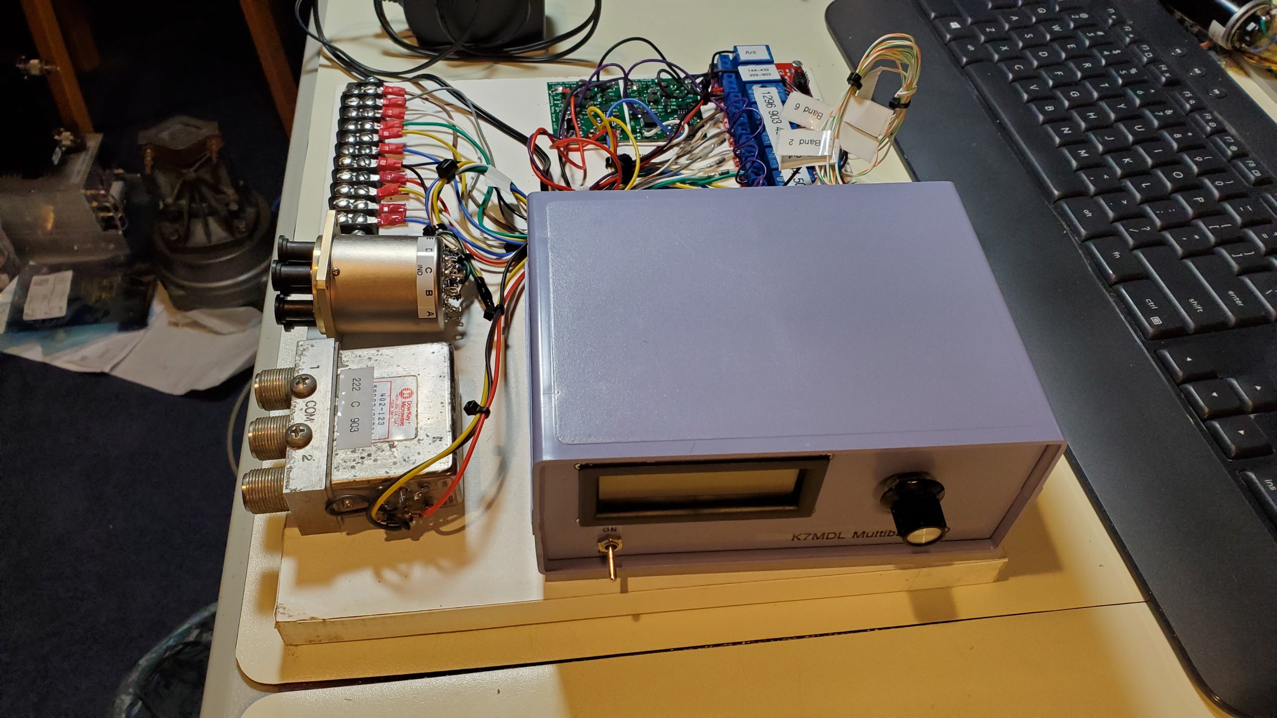
PSoC 5LP based RF Wattmeter for the HF to microwave bands
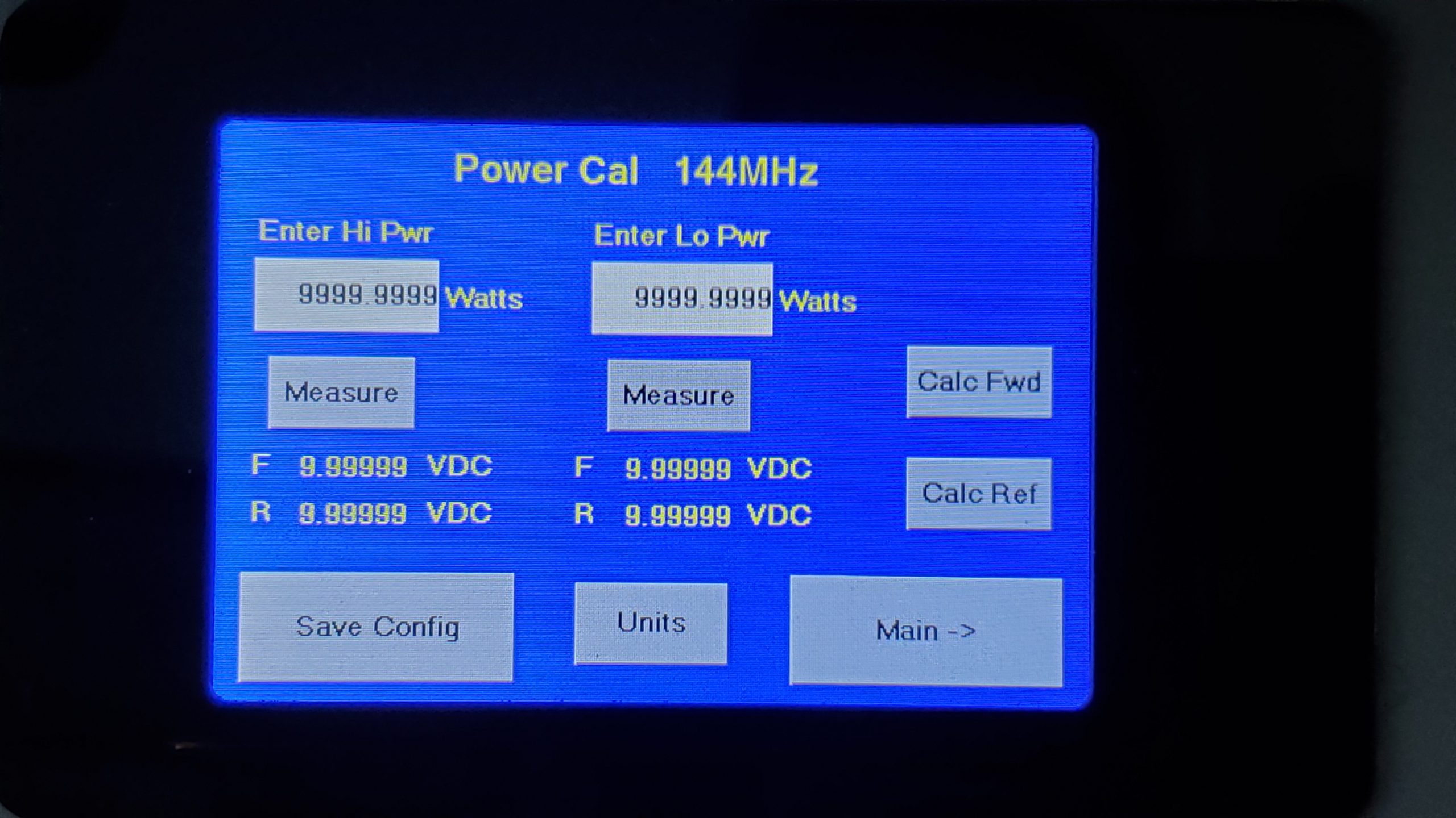
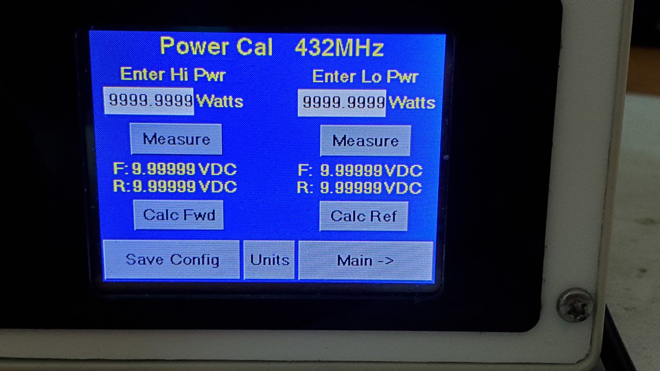
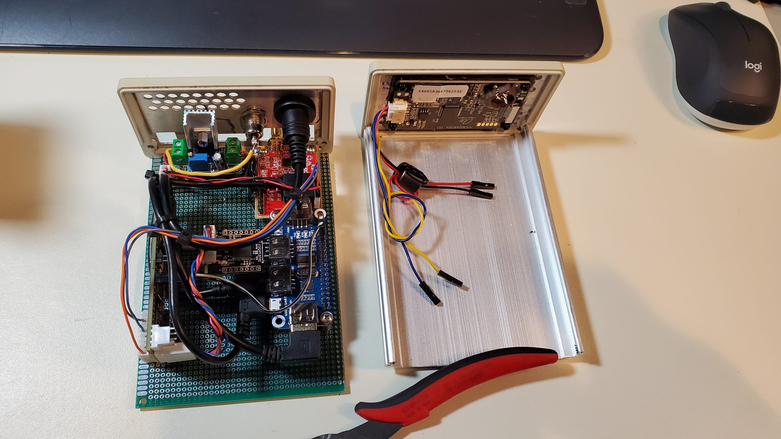
The version I am developing on now is based on the PSoC5 and I have support for 2.4″ and 3.5″ Nextion Intelligent LCD graphics touchscreen displays and 1″ square OLEDs.
OTRSP Band Decoding for Antenna and Transverter selection from a PC logging program. You also get PTT and CW Keying.
Most recently on the PSoC version I added support for serial port control from N1MM+ logging software using the OTRSP protocol to decode serial values to parallel port IO pins, and also present CW and PTT keying from the logger. Other logging programs support OTRSP as well.
The plan is to lift the decoder feature from the wattmeter and make it available on a Arduino Nano with a USB connection and a driver chips to buffer the IO. These parallel IO pins can be used to operate antenna relays or select transverters, sequence PTT switching and send PC generated CW. Each decoder can support up to 2 radios and depending on the number of IO pins available on your chosen CPU module, up to 16 lines per radio plus 1 CW and 1 PTT. BCD coding can be used to make 4 lines represent 16 values if you already have or can accept BCD. This is easily configurable since we control the code.
20201105_222245

20201105_222241

20201105_173818

20201105_173710

20201105_173534

20201105_020831

20201102_171416

20201102_171407

20201101_215403

watching 2 meters
3.5_Cal

3.5_Setting
2.4_Cal

2.4_Main

3.5_Main

20201010_034517
20201010_022713

20201105_173517

20201105_173505

20201103_012130
20201103_012104 1

10Ghz RF Power Meter
20200725_001108

20200724_231938
K7MDL 2.4inch PSoC RF Meter

20200623_020711
20200629_002007
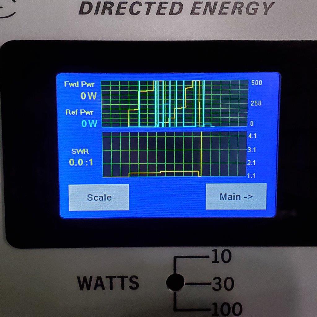
3.5 Graph Screen